First things first. This little red light.
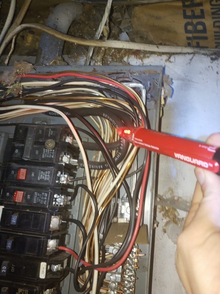
It’s a good light.
This is a Non-Contact Voltage Detector. It senses whether there is electricity flowing to a wire, even if there is no full circuit. It’s generally used to see if a plug, switch, or fixture has power without having to turn it on, or to find breaks in a wire.
It’s detecting, in this case, that our breaker box is powered!
I’m excited.
Now, on to the content.
Electricity? Wuzzat?
I realized as I was writing up the last post about wiring that there are a lot of terms involved in electrical systems. Lots of terms that many people may have heard but don’t really know what they mean.
We’re going full Kevin O’Conner up in here, asking the tough questions.
So let’s back up for a second. What all is involved inside an electrical breaker box? How does that interact with your meter, the utility, and outlets and switches around your house? How does electricity “get everywhere”?
The Load Center
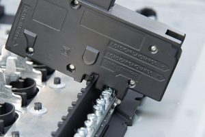
The heart of your electrical system is your circuit breaker box or fuse box, known as a load center. This accepts power from the meter at 220 (nominally 240) volts across two different 110 (120) volt supplies, as well as a path back to the pole, known as the neutral. Inside of the breaker box, the two 110 volt supplies are broken by a main breaker, which is usually 100-200 amps. Modern homes require a 200A load center.
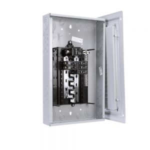
Your basic disrobed and unwired load center.
Woah, slow down!
Amps? Volts? Alright, we’re gonna need some more basics.
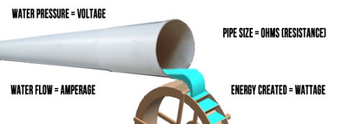
Think of volts as water pressure, and amps as water flow, or the amount of water coming out of a hose. In order to get more amps, you might need more volts. But, you can still use a lot of volts on something that only needs a few amps (if the circuitry is compatible). That’s why you see large devices, like a dryer or an oven, requiring more volts; because it also requires more amps. More pressure, more water!
While we’re on the subject, ohms is a measure of resistance (that’s like the diameter of your water hose), and watts is a measurement of the energy used, which is the product of multiplying volts by amps.
Check out your phone charger for a second. See where it says output? It might say 5.0V 2.0A or something similar, right? If you multiply those, you get 10.0, which is the wattage of that adapter.
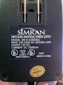
This power brick supplies 30W (12Vx2.5A).
Watts is how the electric meter measures consumption. The electric company turns this into kilowatt hours (kWh) to figure out how many thousands of watts you used in a month.
Now, in many other countries (specifically European nations), the mains voltage is 220 instead of 110. Our math(s) tells us that the same amperage (say, 15A) at double the voltage provides twice the wattage (3300W instead of 1650W)! This means that you could theoretically run more stuff on the same size wire if it were carrying 220V instead of 110V.
Ok, I think I’m following.
Good! There’s plenty of additional resources on basic electrical theory, including this one from which I took some of the above concepts.
Now, back to the breaker box. Inside the box, the two 110V lines are normally separated into alternating tabs in the middle of the box, to which your circuit breakers will connect. Note the snake-like pattern in our disrobed breaker box above. If you need 220V, you would simply connect to both sets of tabs, which is done by “ganging” two breakers together. The appliance must also be wired to use this dual supply properly.
Circuit breakers slot onto the tabs in the center of the box with a variety of pivoting and locking systems. Different manufacturers have different attachment systems. This variance in designs means that if you want to add or replace a breaker, you need to check who your load center manufacturer is and buy the right kind.
Circuit breakers also usually only have one wire coming out, which connects to the black, or hot, wire of a standard cable. Only one connection is needed because the other wires connect to common interfaces: the neutral bus bar and the ground bus bar.
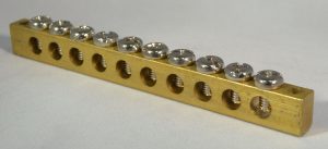
You should already have two of these, one on each side of the box.
All of the white, or neutral, wires in your house will connect back to the neutral bus bar wherever they can fit. These all connect to the bare neutral wire from the meter box, which goes back to the pole, completing the circuit with your power plant.
The bare copper ground wires then all connect to the ground bus bar, which goes to earth via a ten foot copper rod buried outside your house, or via the water supply main. We learned all about that on our last post.
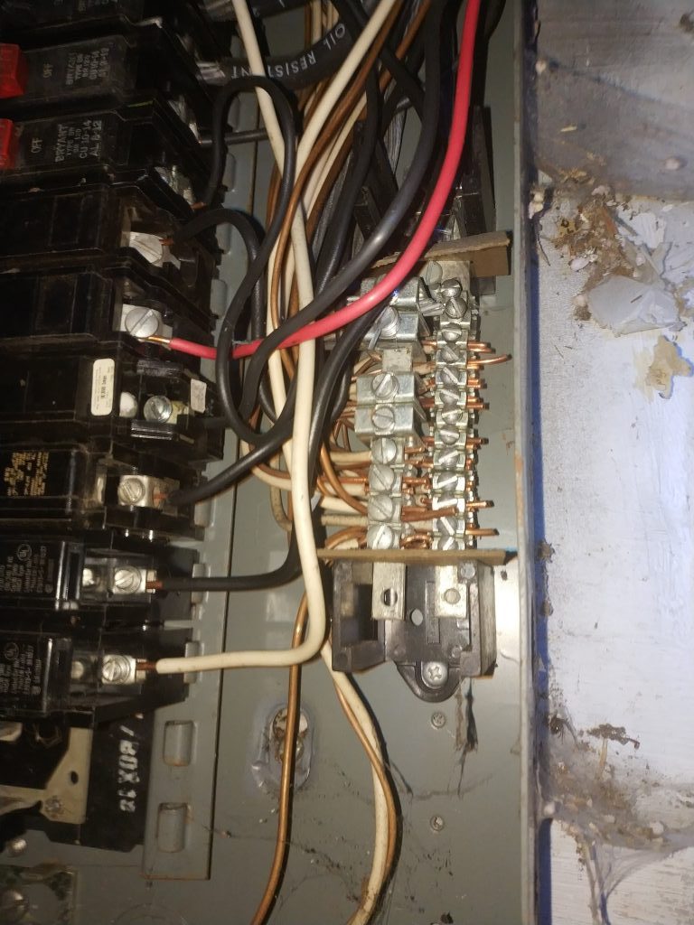
In the case of the hoard, there are two rows, but they are actually mixed together (which is not particularly unsafe, since they are bonded together anyway). This kind of mixing of neutral and ground can only be done at the service panel, never in a sub-panel or at a receptacle.
Ground is really just a backup neutral.
Hey I found this weird breaker though!
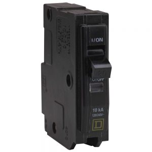
There are some other circuit breaker types which can have more than one wire coming out of them. Let’s look at a standard one first. Nothing special here; power in through the tab, power out of the screw (on the bottom in this orientation):
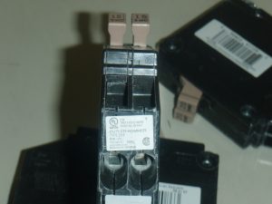
Back in the day, if you had insufficient physical space in your breaker box, but you do have sufficient “space” left in your load calculation for your box, you could install one of these double breakers, which allow one slot to feed two separately protected circuits. These are known as “cheater”, “tandem”, or “thin twin” breakers, and should NOT be installed new. These break the “circuit total limitation” of a load center, and as a result are usually labeled “NON-CTL”. They are sold as replacements for existing applications only.
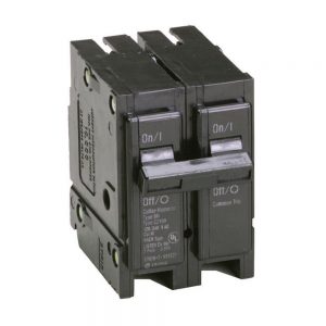
There are also gang-able breakers, which consist of two breakers (or sometimes three, in 3-phase applications), barred together to break all at once if any single element overloads. These are used for 220V circuits, since two breaker slots next to each other vertically would be fed by the two different 110V supplies from your meter.
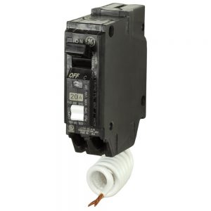
There are also Ground Fault Circuit Interrupt (GFCI) and Arc Fault Circuit Interrupt (AFCI) breakers that you can install to protect a full circuit. This is opposed to installing individual GFCI or AFCI outlets in a kitchen, bathroom, or bedroom, for convenience and cost savings. But, if there is a fault, you have to head to the basement to reset the switch. These breakers have a dedicated extra wire that must be connected to neutral, and also accept the neutral back from the circuit it’s protecting, rather than sending it right to the bus bar. This is so it can measure the amount of electricity it sends and receives, and look for any discrepancies.
Alright, that takes care of the breaker box. What happens on the other end?
Not so fast, Kaiba. The wires in your house are routed through the floors and walls to reach the intended electrical location. This routing has to happen in a specific way so that wires aren’t accidentally pinched, stepped on, nailed into, dangling, interfering with other systems, or touching gas lines. And of course, the wires have to be insulated against each other.
There is really only one kind of jacketing, or insulation, you would see on wires today, which is “NM”: non-metallic sheathed cable. This is typically three or four strands of wire in various gauge, coated in vinyl, which basically lets it be run anywhere inside without additional insulation. The conductors themselves are also individually coated with plastic, and then wrapped in paper before being dipped in vinyl.
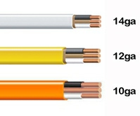
14-2, 12-2, and 10-2 NM cable.
The color of the jacket indicates the gauge of wire, with white being the most common gauge of 14 for regular circuitry around the house (15A breakers), yellow 12 gauge for heavier applications like a workshop, kitchen, or bathroom (20A breakers) and orange 10 gauge for large appliances like the dryer or stove (30A breakers).
These NM wires come in designations like “12-3”, which means that it is 12 gauge wire with three primary conductors, plus a bare ground wire. The first two strands are always black and white, while a third conductor is colored red. A fourth wire, on, say, a 14-4 cable, would be blue. These extra wires are used for controlling circuits in various applications, like making a 3-way switched light, a motion-detecting light, or a hardwired smoke detector system. The bare ground wire is not counted in the wire’s designation, so if you cut open 10-2 wire and see three conductors, you’ll know why.
Older wires might be covered in rubber and then wrapped in cloth. Older still is the legendary “knob and tube” wire system, where individual strands of cloth-taped wire are run in parallel through porcelain tubes and hold-down knobs. This stuff is actually very well made (splices are specified to be fully soldered, for instance), but its age means the insulation is probably cracking and falling off, and it should probably not be reused if you are making any changes.
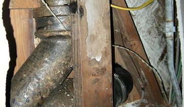
The actual copper conductor rarely breaks down, it’s always the rubber or cloth. If left alone with no regular movement, it could hold up for quite a long time. However, eventually, the insulation will crack or shrink, exposing the leads of the wires, which can cause faults. This is particularly apparent inside of junction boxes, like the one below, where fixtures were possibly replaced, necessitating the movement of the wires, causing breaks.
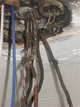
Its clear why you might need to replace old wiring. These used to be rubberized.
The hoard consists of a mix of modern NM and some semi-modern cloth covered wire, probably installed around the 1960’s. That doesn’t mean there’s no knob and tube, though. It might be running in the walls, but wired in junction together with new stuff somewhere before it hits the basement.
Where wires are run in existing walls, called “old work”, they are just left floating, and attached wherever possible. In new builds, aka “new work”, wires are to be held down and protected wherever possible. Wiring generally is attached to studs or joists wherever it is run using metal staples, sometimes with a plastic insulator to prevent pinching.
How about when you need to put wires outside?
If wires have to run outside the building, or down through mid-air (like to reach your hot water heater or furnace), or really anywhere out in a living space, they must be protected. There are two main ways to take care of that.
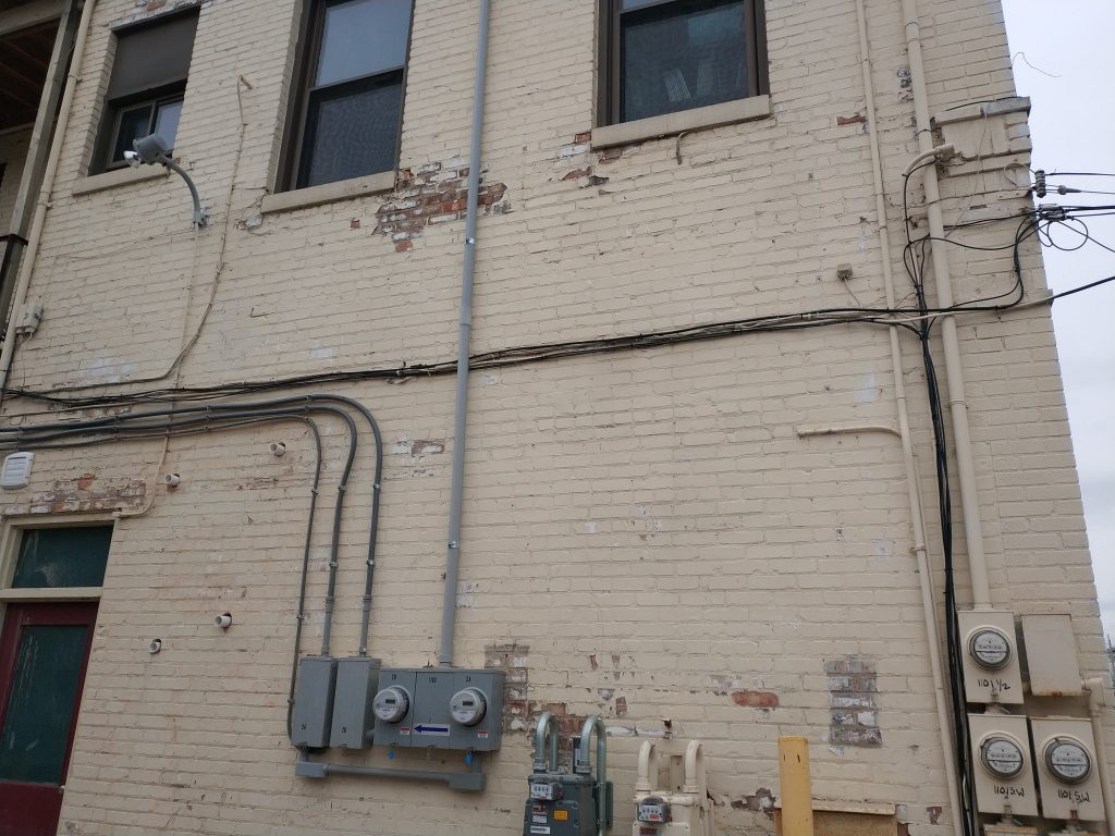
The first is to use rigid conduit, which could be steel, galvanized, aluminum, or PVC. This option is a cleaner look and best for runs around a building where you have sufficient space to add the piping. It’s also needed for your power mast, the tube coming out of the top of your meter box. This keeps the mast immobile so it won’t whip around in the wind, and it can also be made waterproof.
The second option is to use flexible conduit, which could be HDPE plastic (good for use underground), or spiral-wrapped metallic sheathing, called armored cable. Armored cable is good for areas where you are bringing electricity down to an appliance, like to a furnace or hot water heater (its most common applications), or where there is going to be vibration, like to an air conditioner. It’s also easier to install inside a wall or in a tight space, though the flexibility causes a less-clean finished product.
Plastic-dipped armored cable on the left, rigid PVC in the center, and rigid galvanized conduit on the right.
Awesome! What about plugs and switches?
Oh, I think that’s enough of a lesson for today, don’t you?
Next time we chat, we can talk about how all of the outlets in your house are actually upside down, which wire to put your switch on, how to size up the load on a circuit and house, and some common wiring diagrams and procedures. Hopefully, I can even walk you through a plug or two in the hoard by then, especially now that THE POWER IS ON!