Did you all pick up a course syllabus when you came in? Good, let’s get to page 34 in our textbooks and dig into this practical.
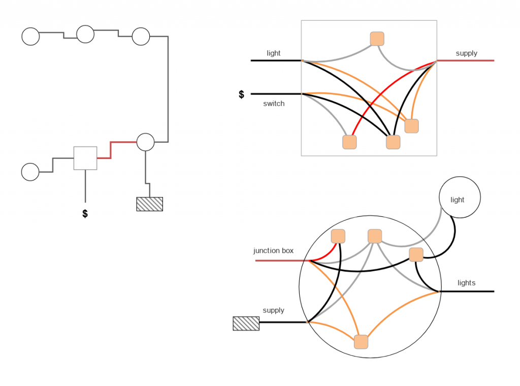
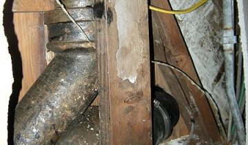
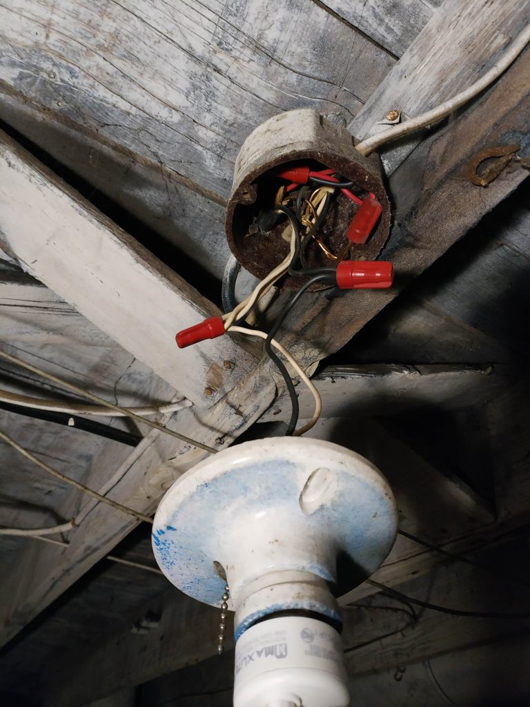
I take it you all remember this image from my last post with fondness. On the left, an overhead view of the basement light circuit. The grey shaded box is the circuit breaker panel, with a wire marked “supply” coming from it. There are other black wires that lead to the various lights, marked with black circles. Finally there is a single-pole (basic on/off) switch, marked with a dollar sign. Let’s ignore the other two drawings for now; I’ll draw your attention first to the wire marked in… uh, what is that, rust?
The Wiring 101 post, specifically the section on wire gauge, may come in handy here. The rust colored wire (which isn’t actually rusty in real life) is a 14-3 wire. This has an extra conductor in it, which is red.
This is PERFECT in my application, where the power comes into the circuit at one junction box, but the switch is on another junction box, and we need to transfer that power over. Rather than running a whole second wire, or re-running the supply, someone else had the forethought to add this 14-3 wire. The remainder of the wires are all 14-2, 14 gauge being just fine for the amperage we’ll be drawing.
Analyzing the circuit
I did not invent this wiring circuit, so I can’t take all the credit. But it does need to be put back together.
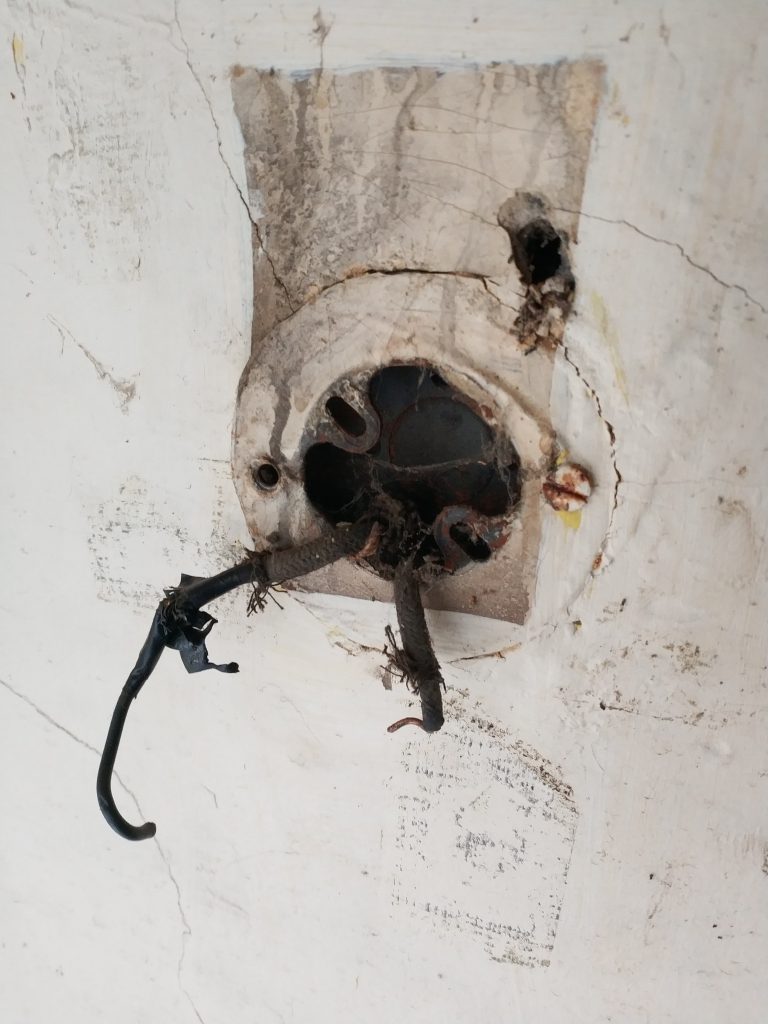
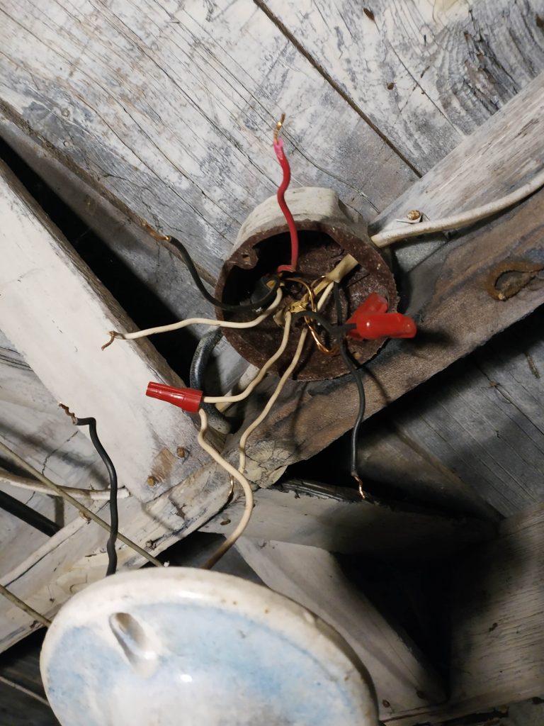
I followed the wires coming out of this junction box, and one of the goes into the breaker box. That’s gotta be the supply for this branch. The other wires go into individual openings in the junction box, which makes it easier to shift the wires and see where they lead.
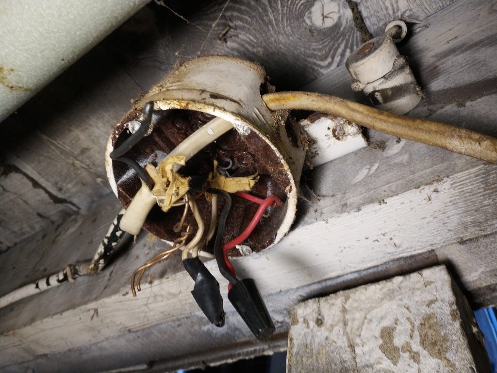
The box above is where the switch used to be. But, someone removed it and just wired the two other leads together, albeit incorrectly. The old knob and tube wiring is on the right, disconnected from everything.
Once I had a mental picture of the circuit, I then figured out where I wanted the electricity to flow and adjusted the connections to suit my needs. I grabbed a handful of nuts, for energy, and also a handful of wire nuts, and got to organizing.
Setting up the circuit
Here’s that diagram again.
Our switch needs to be in series with the power for the whole circuit. Let’s start at the round diagram in the bottom right. From the supply, the black (hot) wire goes to the red (extra) wire of the 14-3 wire heading to the junction box for the switch. At this junction box (the square diagram top right), the red wire, which is directly powered from the supply, goes into the white wire of the switch.
I picked the white wire so I can know that the black wires all go together later. Traditionally, when a wire is run to a switch, the white conductor is given a black stripe of tape, to indicate its purpose.
The black wire from the switch, then, can be put into our load, which is all of the lights in parallel. All the remaining black wires go together, and all the white (neutral) wires will go together as well. This is the same in every junction box in this circuit, not just the ones pictured. And, without exception, all ground wires from every wire go together.
Hey you skipped a step!
I did. I mentioned that the switch was missing, right? Let’s get that back in!
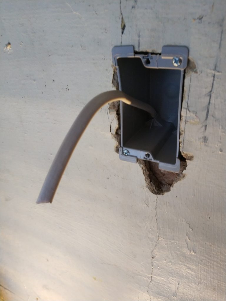
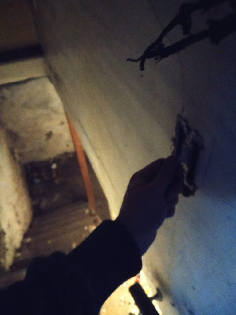
I agree angsty AJ, let’s not use this box again. This is a very shallow box called a pancake box, which is really only used in real old ceiling applications. I can’t fit a switch in there. We’ll need to cut a new box in.
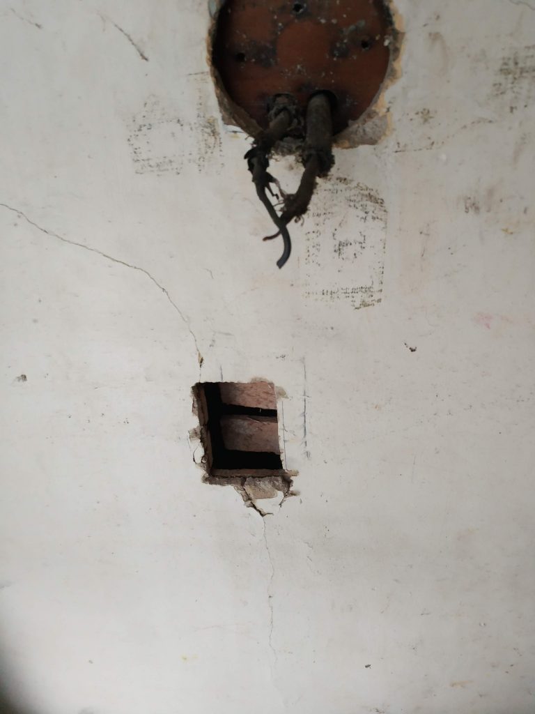
I checked inside the wall for the closest studs using a piece of wire (or a coat hanger in a pinch), and it seems that this box was right between them. I had pretty free reign as to where the box goes, as long as its a comfortable height, vertical, and reachable. This is about 4 feet off the landing.
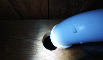
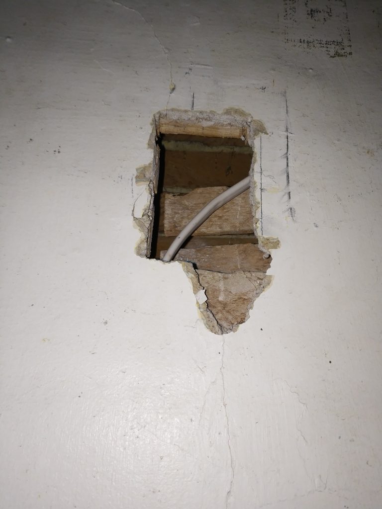
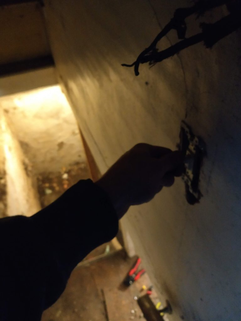
I made sure the box will fit, but didn’t install yet. We need to run the wire first. I drilled a 3/4″ hole up from the basement into this wall cavity using a spade bit, and fed the wire up, enough to go past the hole.
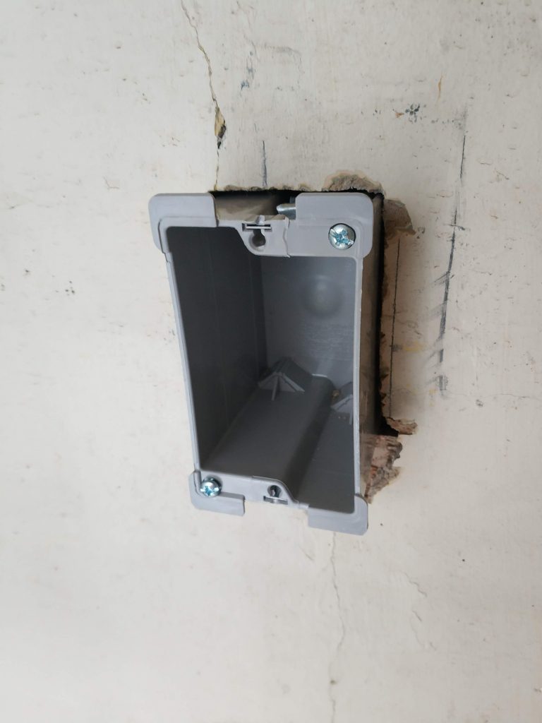
Reach in and grab the wire, and bend it over so it doesn’t go anywhere while we get the box. I fed the wire into one of the holes in the box, which are self-retaining, and added the box to the wall. This is an “old work” box, which has little ears on screws that hold the box to the wall. This is opposed to “new work” boxes, which have nails, and should be added before drywall or plasterboard go up.
Strip off the plastic coating, and about an inch of the insulation at the end of each wire, then use some needle-nose pliers to curl the ends of the three leads. Now it’s time to add the switch.
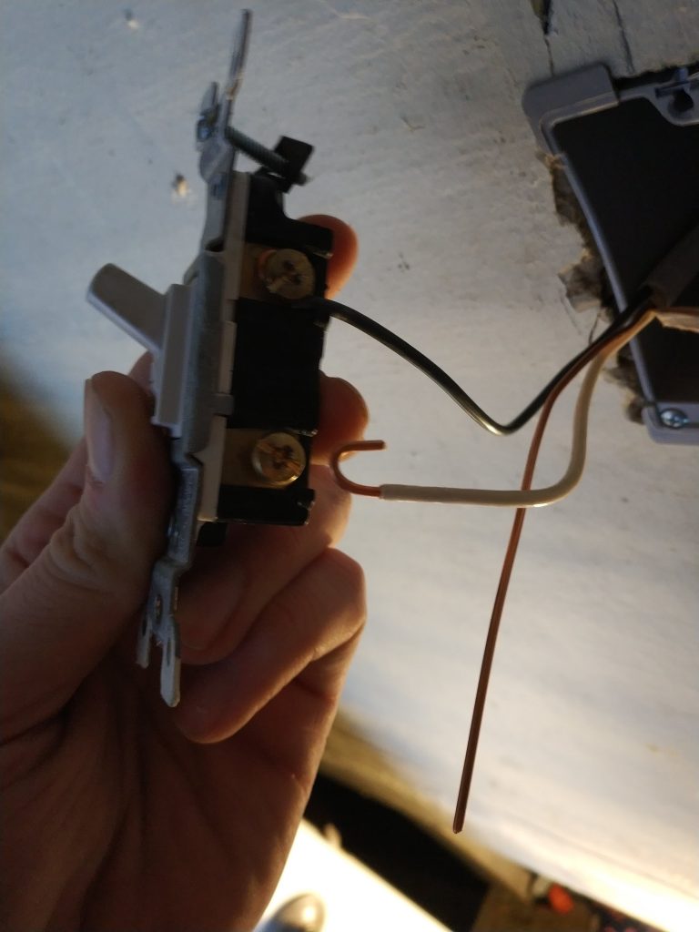
Easy! this part is 100% done!
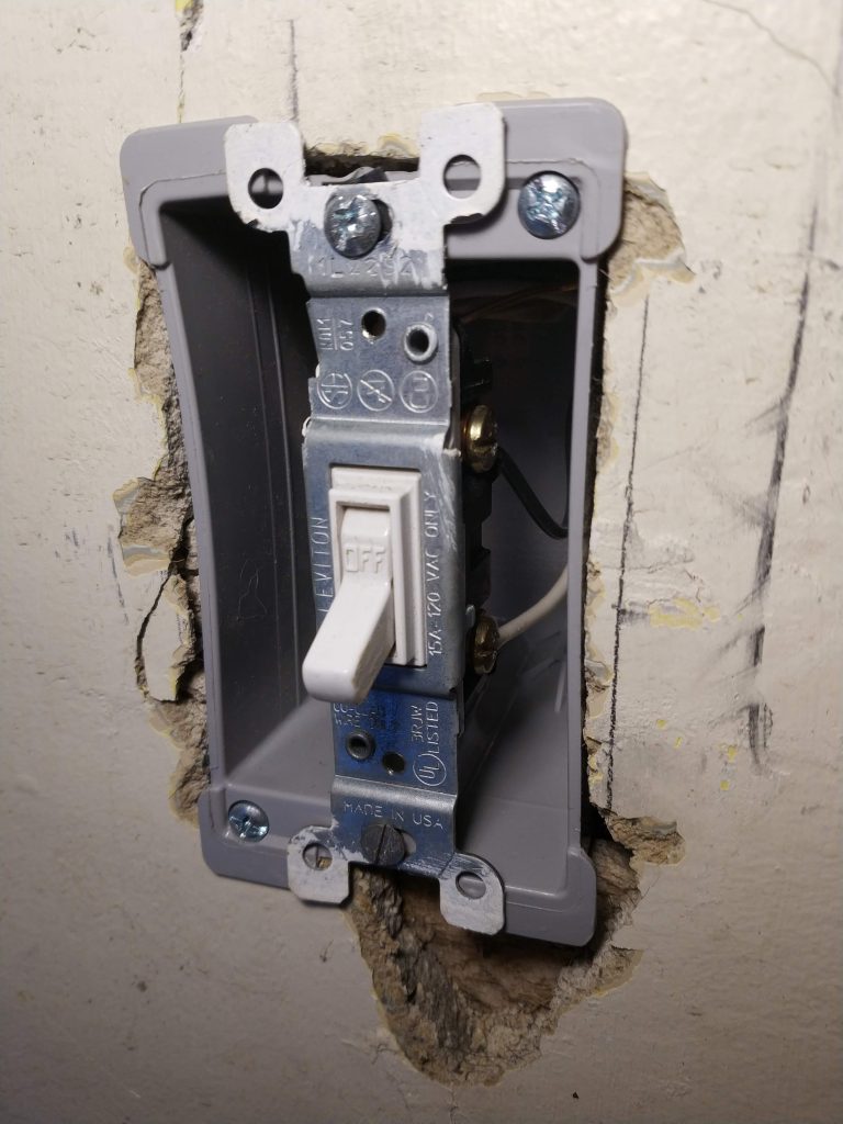
This switch is rated for a full 15A, so it could switch up to 1800 watts! These lights will be no trouble.
The rest of the circuit
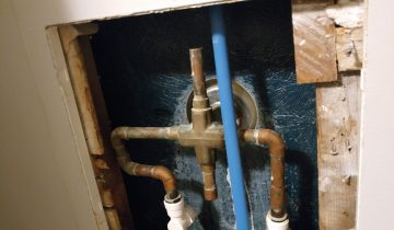
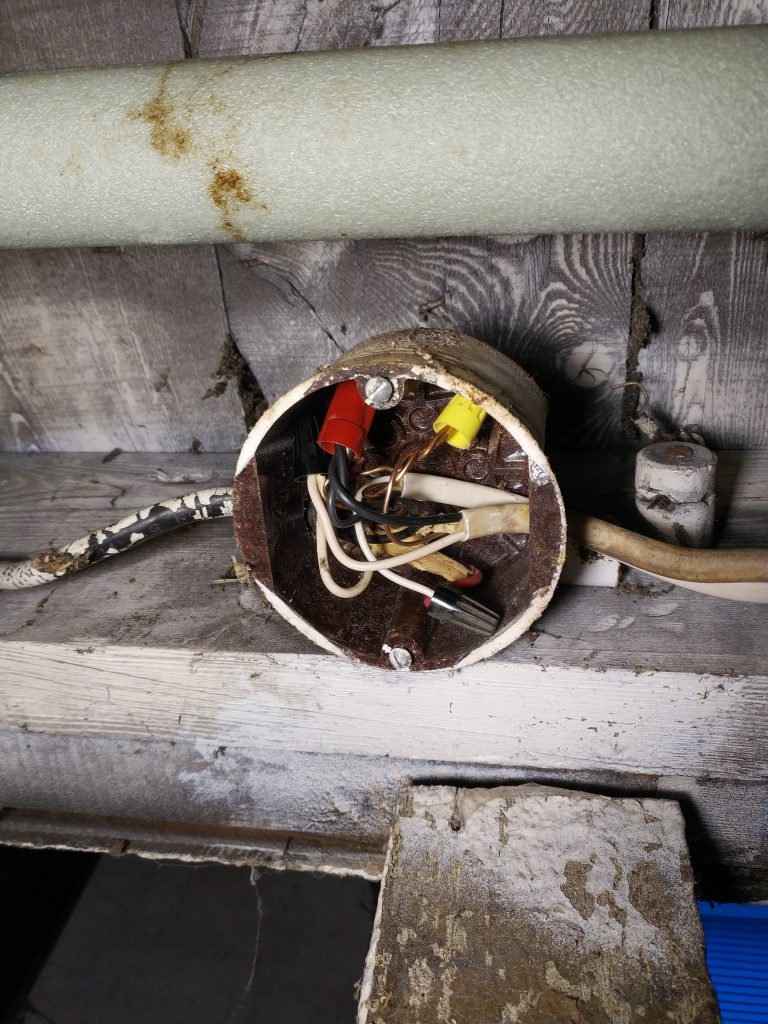
The remainder of the circuit was already wired up properly, other than the supply box we dug into earlier. I disconnected everything in here to get a good starting point.
Per our diagram, I connected the hot supply to the red wire, then all the black wires together, and all the white wires together, including the short leads going to the local light fixture.
And the moment of truth. I turn on the breaker to this branch.
…
Nothing happens.
Which is good, because the switch is off. If something made a smell or a noise or turned on, I’d be surprised.
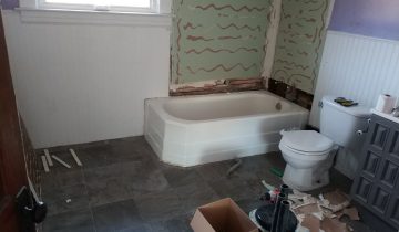
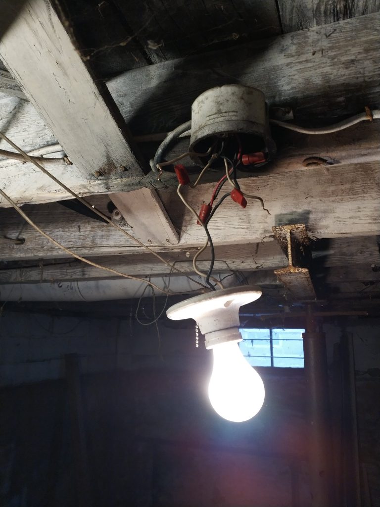
It works! A few bulbs later, and we have a basement full of lights!
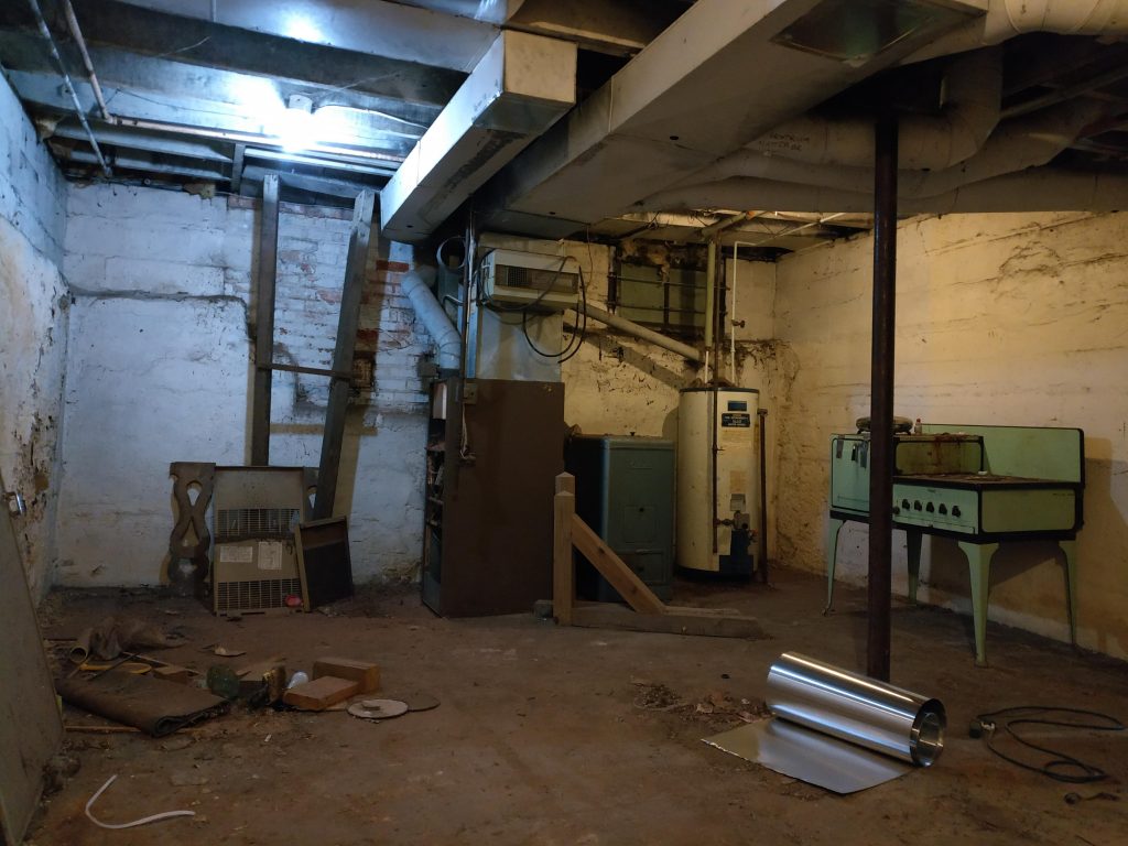
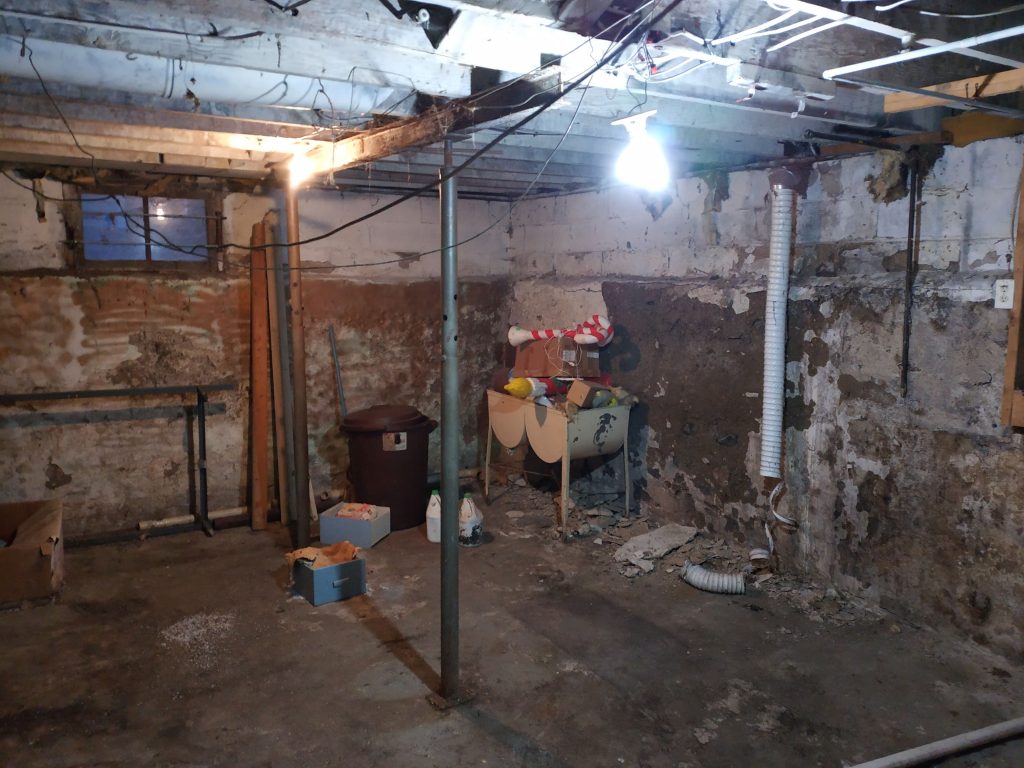
Yes, but a brightly lit pit!
Hoorah!
It’s a big moment for the hoard. I don’t think it’s seen the light of… light for about a decade.
A few potential questions popped into my head while writing this, and they didn’t fit anywhere other than here, so here they are!
What are the wire nut colors for?
Different colored nuts hold different numbers of different gauges of wires. Red nuts are about the largest for residential, then yellow, then orange or black, and finally blue. Too large of a nut, and it will just fall off. Too small and it won’t be able to encompass the number of wires you are binding. The package of nuts should tell you the number of wires that each will hold. For instance, a yellow nut will hold a minimum of two 18G wires, and a maximum of four 14G wires. I like to use orange nuts for two wires, yellow for three, and red for three or four. But, yellow nuts can do it all, if you have enough room in the box.
Do you need to tape the wire nuts?
If you are worried about a wire poking into the nut later on, sure, or if your junction box is particularly cramped. But indoors, I think putting electrical tape on wire nuts is a waste of time. I’d be much more concerned about putting tape around the sides of a plug or switch, which has exposed screws, in a crowded or metal box.
How hard do I crank these things down?
I screw the nuts on enough to start twisting the insulated parts of the wires together. I’d say it’s about as hard as you need to twist to take the top off of a new 2 liter of pop. Give each of the wires a little tug to make sure they don’t come out. If you think it’s not on there good enough, it’s probably not.
I’m worried this junction box is too full.
It’s hard to say when a junction box is too crowded, because they can fit quite a bit. Wires are insulated well and can be jammed right next to each other with no problem, as long as there’s no nicks or bare bits. You might have to cram the wire nuts up into the corners to make everything fit, and also be sure you can attach the screws for your plate without accidentally piercing any wires. But, if you really have too much trouble putting the cover on the box again, they do make box extenders to give you a bit more space. I would say that if you have more than 5 wires coming into a junction box, you might want a roomier one.
Does it matter if the lights go first or the switch goes first?
YES! One would always want to switch the supply (hot) side of the circuit. This is in case you need to replace a bulb or otherwise accidentally make a short circuit; the unswitched power could jump to ground and complete the path to the breaker box, shocking you. It’s safer to stop the electricity sooner rather than later in your circuit, and put the switch before the load.
How much insulation do I strip off of the wires?
You only want as much bare wire as you need, and no more. Most plugs and switches will have a stripping gauge on the back to tell you now much wire you need, if you are using push connectors. Trim off any extra conductor you accidentally expose. For wire nuts, you should see no bare wire if you look at it from underneath. If you do, trim the errant wire down, or tape the nut.